The 35-DS3CHIPDUS3 is a specialized hardware component often found in high-performance computing environments or specific industrial automation setups. While the alphanumeric string might look daunting, the installation process is straightforward if you follow a methodical approach. This guide provides a step-by-step breakdown of how to integrate this unit into your system effectively.
Understanding the 35-DS3CHIPDUS3 Component
Before diving into the installation, it is crucial to understand what you are handling. The 35-DS3CHIPDUS3 is designed for high-speed data processing and signal distribution. Because it operates on sensitive logic gates, physical handling requires care to avoid Electrostatic Discharge (ESD).
Key Features:
- High Thermal Tolerance: Designed to operate in environments with fluctuating temperatures.
- Modular Interface: Allows for quick swapping in enterprise-grade server racks.
- Signal Integrity: Built-in shielding to prevent electromagnetic interference (EMI).
Pre-Installation Requirements
Preparation is the most overlooked step in hardware installation. To install the 35-DS3CHIPDUS3 successfully, you need the right tools and a controlled environment.
You Might Also Like: Repmold Mastery
Required Tools:
- Phillips Head Screwdriver (Size #1 or #2): For securing the mounting brackets.
- Anti-Static Wrist Strap: To protect the internal circuitry from static electricity.
- Compressed Air: To ensure the slot is free of dust.
- Thermal Paste (if applicable): Only if the unit requires an external heatsink.
Environmental Checklist:
- Power Down: Ensure the host system is completely powered off and unplugged.
- Clear Workspace: Use a non-conductive surface like a wooden table or an anti-static mat.
- Lighting: Ensure you have a bright LED light source to see the pin alignments inside the chassis.
Step-by-Step Installation Guide
Step 1: Accessing the Interior
Begin by removing the side panel or the chassis cover of your machine. Most systems housing a 35-DS3CHIPDUS3 will have thumbscrews or a latch mechanism. Once open, locate the primary interface slot designated for this chip module.
Step 2: Preparing the Slot
Check the slot for any debris. Even a tiny speck of dust can interfere with the connection points of the 35-DS3CHIPDUS3. Use a quick burst of compressed air to clear the area.
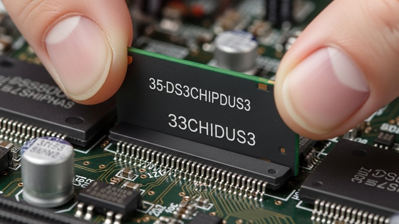
Step 3: Aligning the Module
Hold the 35-DS3CHIPDUS3 by its edges. Never touch the gold-plated contact pins. Align the notch on the module with the key in the slot. Alignment is critical; forcing the component in the wrong direction can result in permanent hardware failure.
Step 4: Seating the Component
Once aligned, apply firm, even pressure on both top corners of the 35-DS3CHIPDUS3. You should feel a distinct “click” as the side retaining clips lock into place. If the clips do not engage automatically, gently push them inward until they snap over the module’s edges.
Step 5: Securing and Cooling
If your specific configuration requires a secondary bracket, screw it into the chassis frame now. If the 35-DS3CHIPDUS3 generates significant heat, ensure the airflow from the system fans is directed toward the module’s integrated heatsink.
Software Configuration and Drivers
Hardware installation is only half the battle. For the system to recognize the 35-DS3CHIPDUS3, you must update your BIOS/UEFI and install the necessary drivers.
- Boot the System: Plug in the power and turn on the machine.
- Enter BIOS: Press F2, Del, or F12 during startup to verify that the hardware is detected at the firmware level.
- OS Recognition: Once in your Operating System, navigate to the “Device Manager” (Windows) or “System Profiler” (macOS/Linux).
- Driver Injection: Download the latest firmware package for the 35-DS3CHIPDUS3 from the manufacturer’s official portal. Avoid third-party driver update software.
Troubleshooting Common Issues
Even with a perfect physical installation, you might encounter hurdles. Here is how to resolve them:
| Problem | Possible Cause | Solution |
| System won’t boot | Component not seated | Re-seat the 35-DS3CHIPDUS3 firmly. |
| Blue Screen / Kernel Panic | Driver conflict | Boot in Safe Mode and reinstall drivers. |
| Overheating | Poor airflow | Check if cables are blocking the module’s intake. |
| Device not found | Disabled in BIOS | Enable the specific PCIe/Interface slot in settings. |
Maintenance and Long-term Care
To ensure the longevity of your 35-DS3CHIPDUS3, perform a biannual check-up. This includes:
- Dusting: Use compressed air to prevent thermal throttling.
- Firmware Updates: Check for security patches every quarter.
- Connection Integrity: Ensure vibrations haven’t loosened the mounting screws.
The 35-DS3CHIPDUS3 is a robust piece of technology, but it relies on a clean, stable environment to function at peak performance. By following these steps, you minimize the risk of hardware damage and maximize the efficiency of your system.
You Might Also Like: Soutaipasu
Safety Precautions
Always remember that working with internal components like the 35-DS3CHIPDUS3 involves electricity. Never attempt to install or remove the module while the “Standby LED” on the motherboard is lit. This indicates that residual power is still flowing through the circuits, which could short-circuit the 35-DS3CHIPDUS3 instantly.
Summary of the Installation Process
Installing the 35-DS3CHIPDUS3 requires a mix of physical precision and software configuration. From the initial grounding of your body to the final driver update, each step ensures that the 35-DS3CHIPDUS3 integrates seamlessly with your existing infrastructure.
By taking the time to properly align and secure the 35-DS3CHIPDUS3, you guarantee a high-speed, reliable computing experience for years to come.
Note: If you are uncomfortable performing these steps, consult a certified technician to handle the 35-DS3CHIPDUS3 installation for you.